Skeatz Mods
Skeatz Mods was created by Mr Steven Chew to facilitate
the generation of 2D CNC Milling
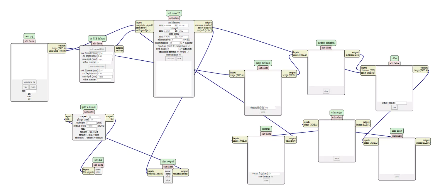
Overview
All the various settings and toggles to fine-tune the
g-code
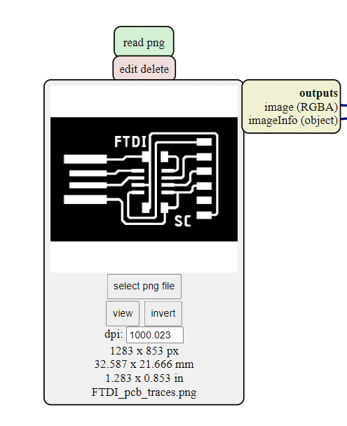
FTDI Traces
My FTDI PCB board design provided by Mr Steven Chew
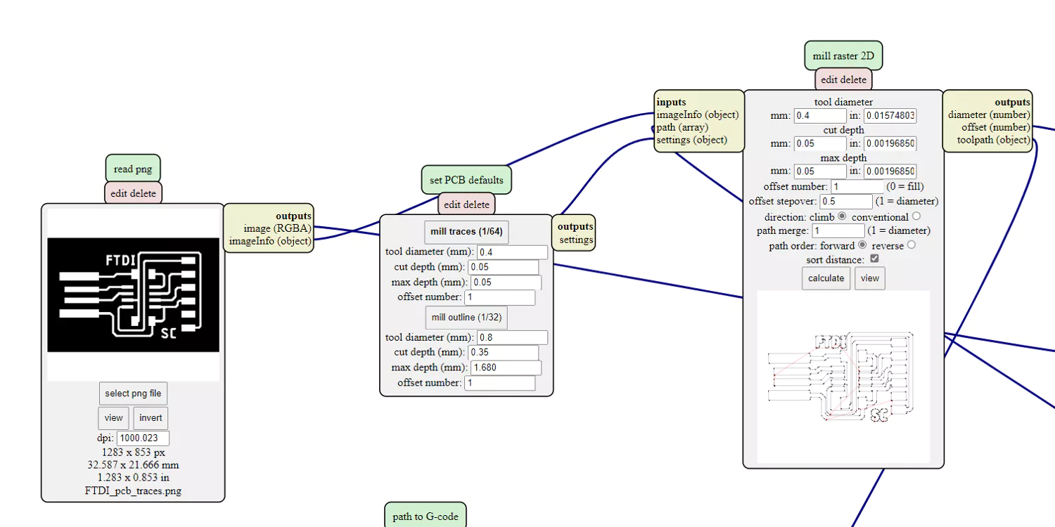
FTDI Settings
FDTI G-code settings
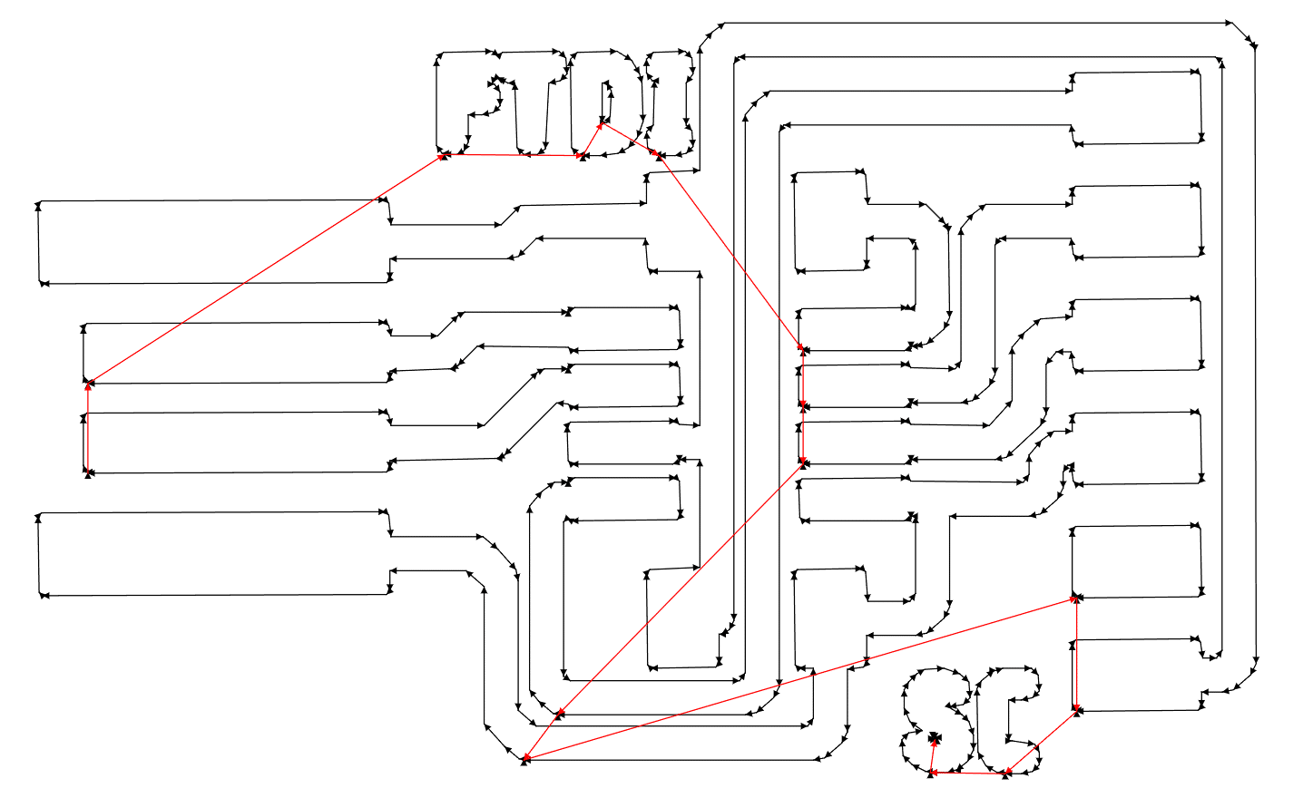
FDTI Toolpath
The FDTI toolpath generated
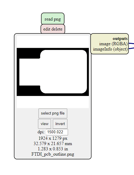
FDTI Outline
To remove the FDTI board from the copper
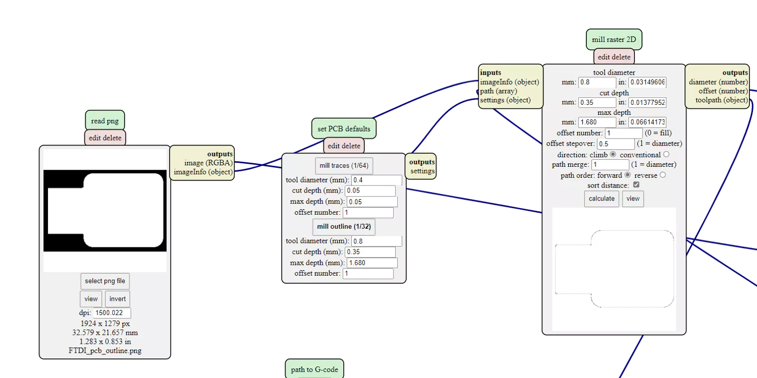
FDTI Outline Settings
FDTI outline G-code settings
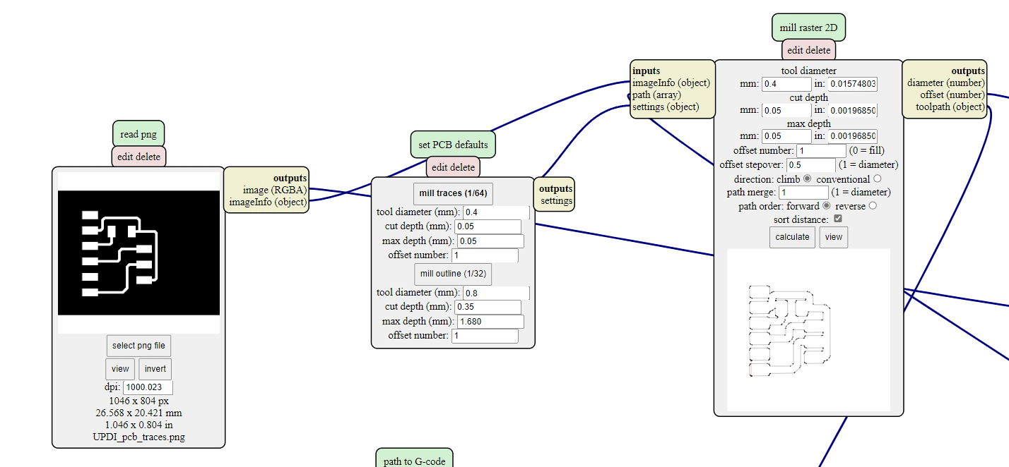
UPDI Settings
UPDI G-code settings
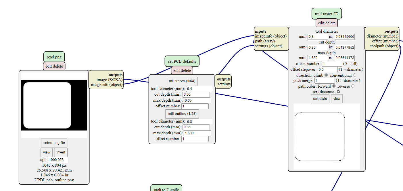
UPDI Outline Settings
UPDI Outline G-code settings
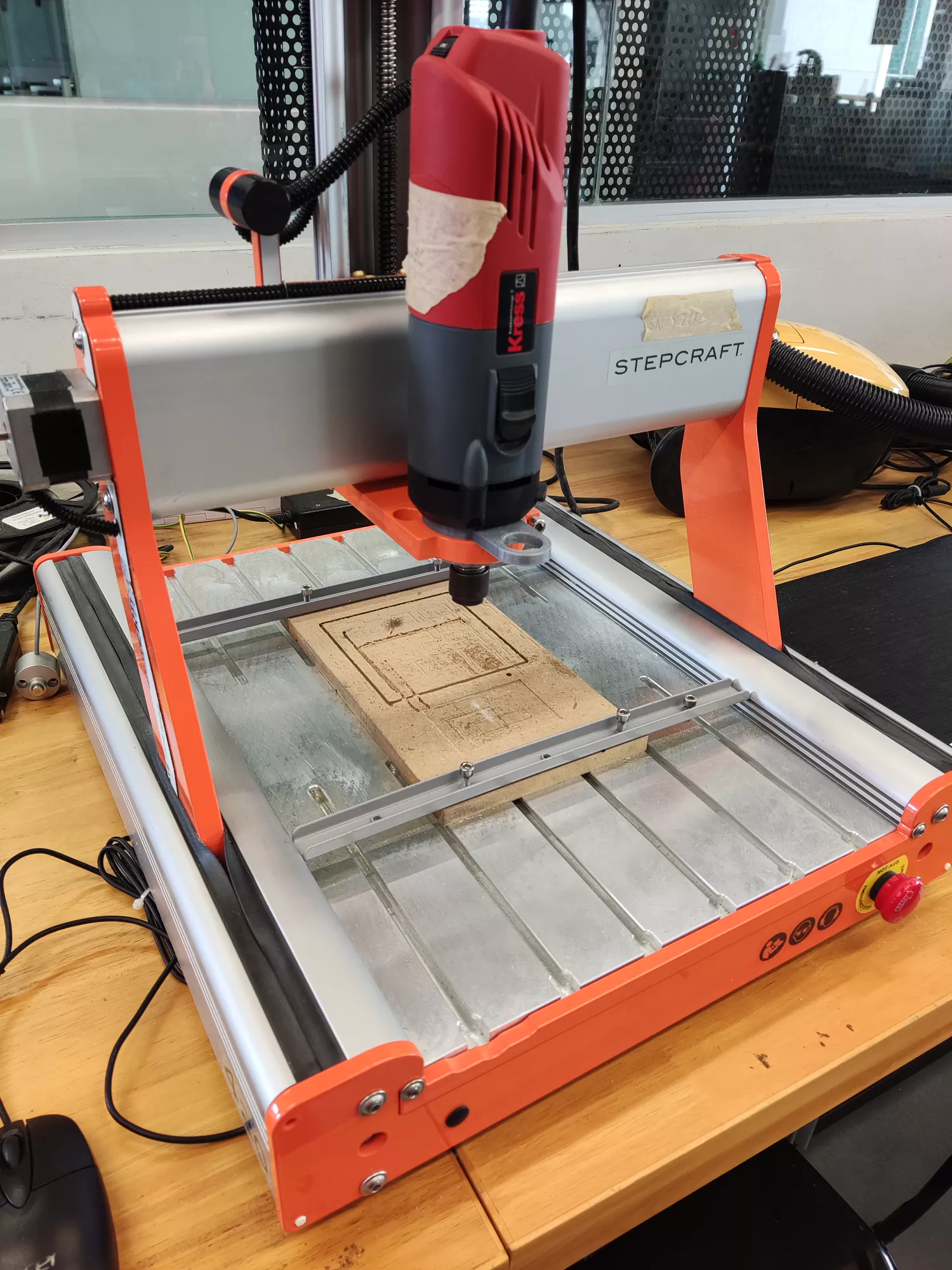
Stepcraft 420
The desktop CNC machine used for PCB milling
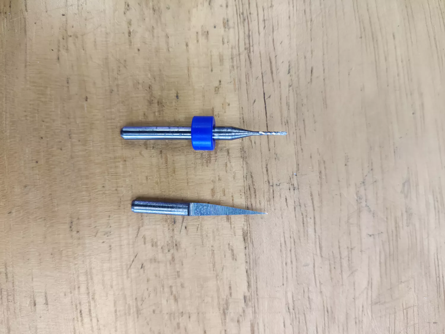
Drill bits
0.8mm flat endmill & 0.1mm 10deg engraving bit
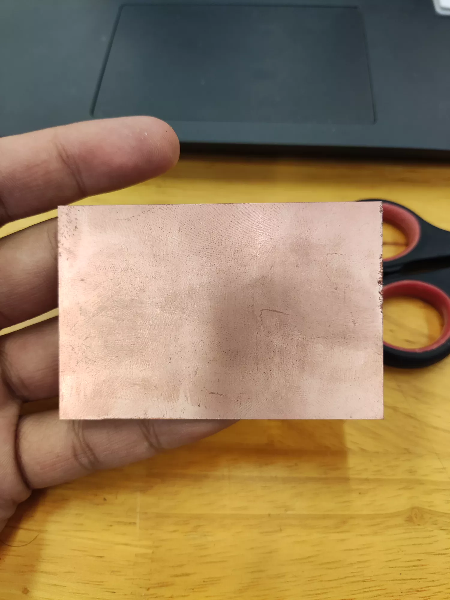
Copper Board
A thin layer of conductive copper
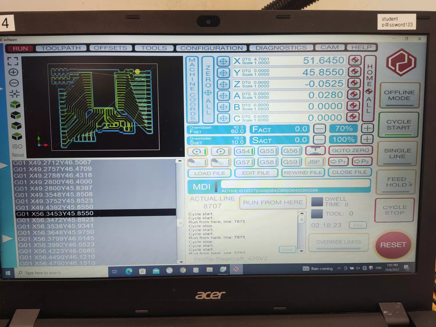
CNC Software
The controller for the Stepcraft 420 CNC
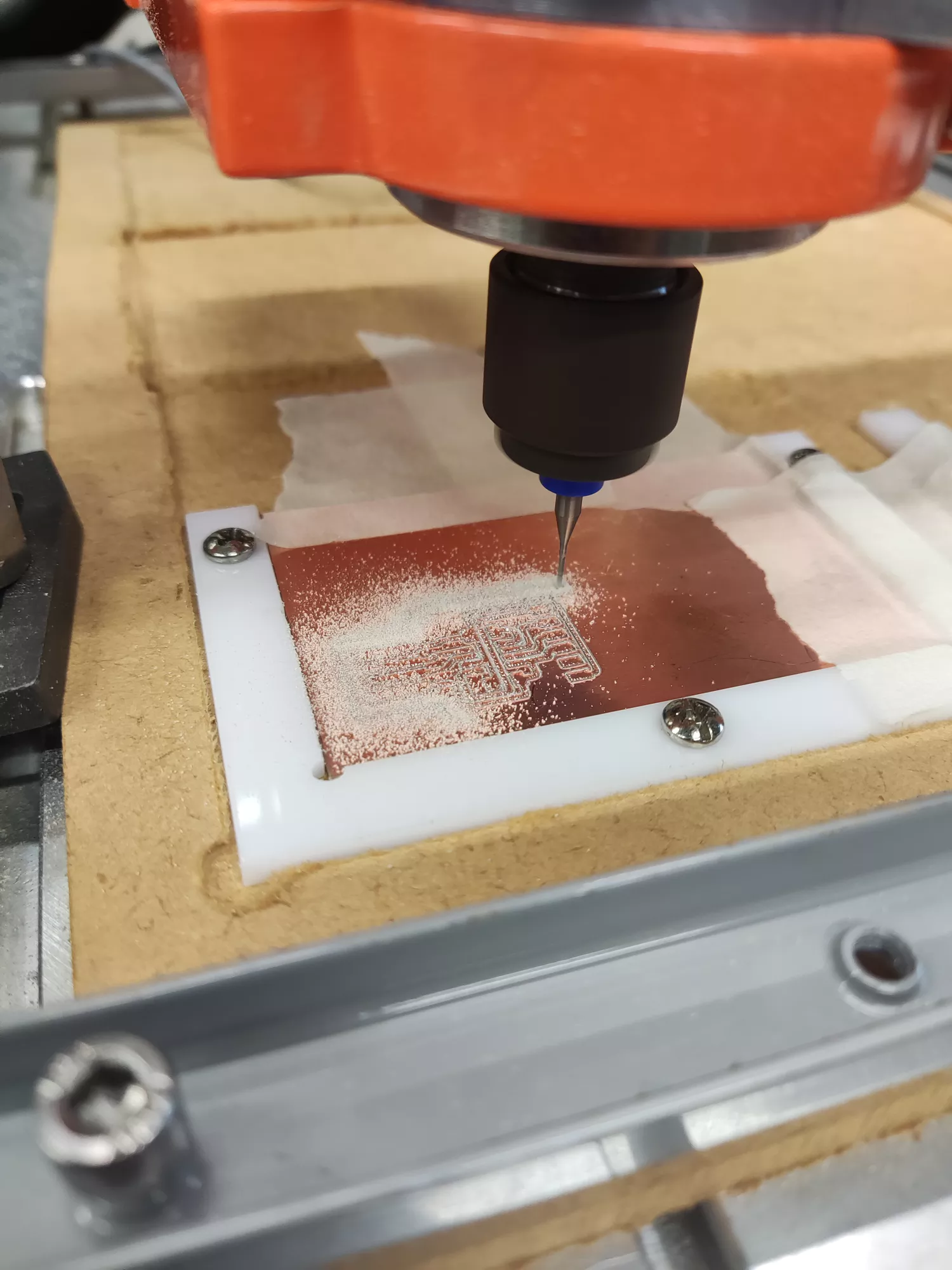
Milling of FDTI PCB
.
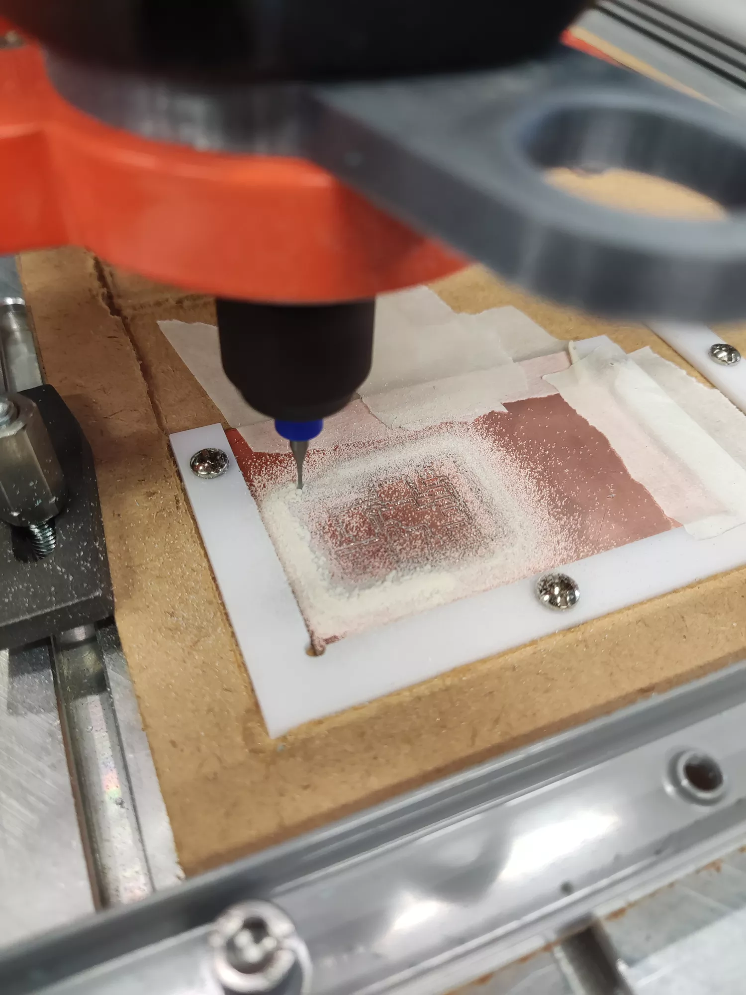
Milling of UPDI PCB
.
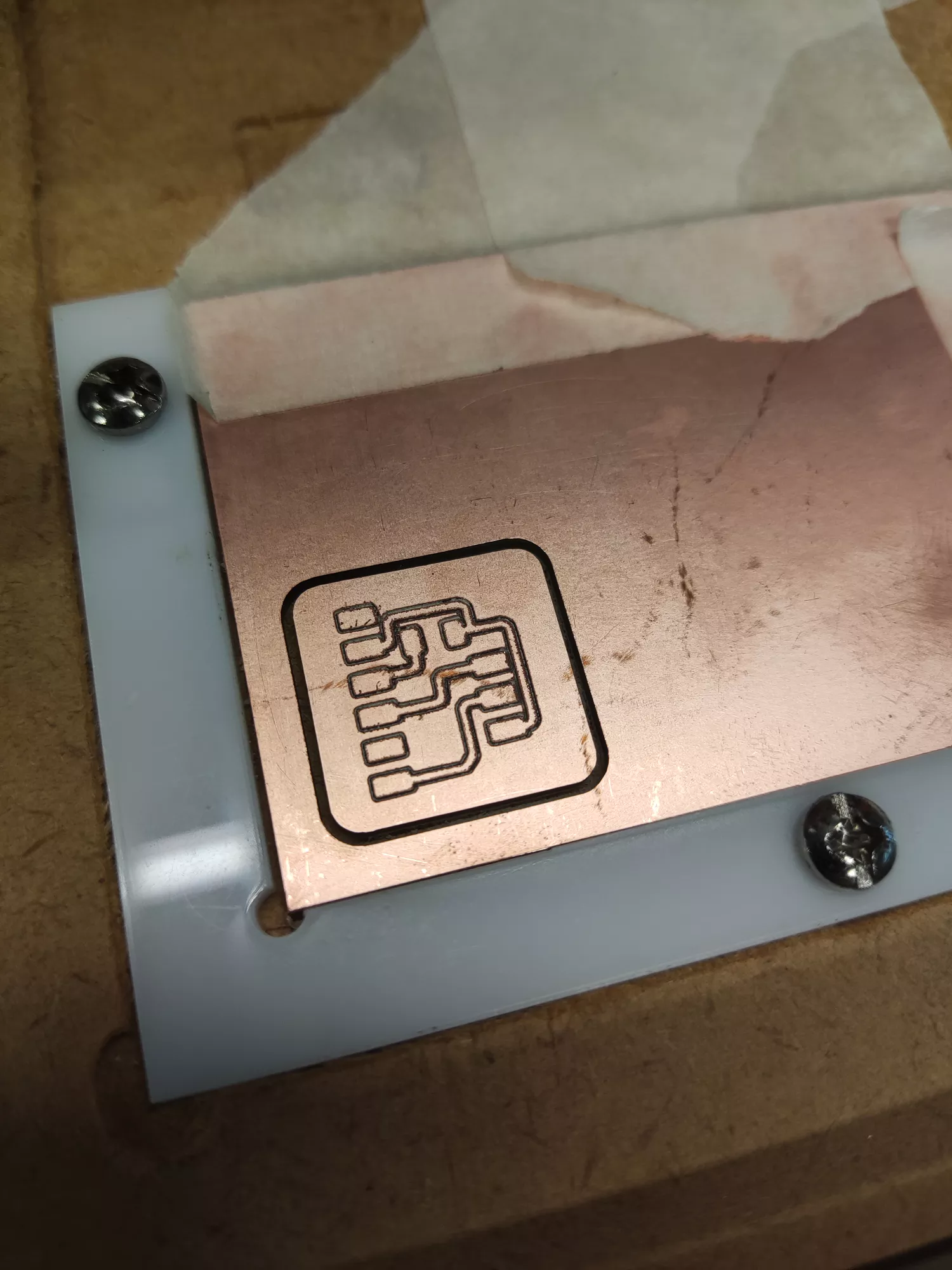
Completed UPDI PCB
crisp, sharp edges along the traces
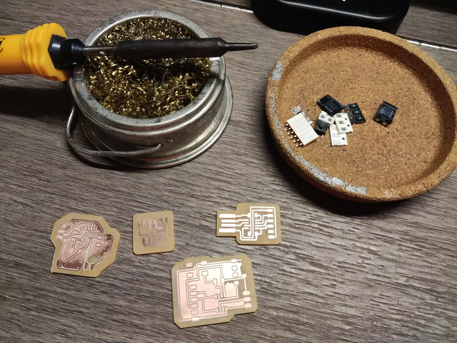
Soldering Preperation
Soldering Iron, flux and various components
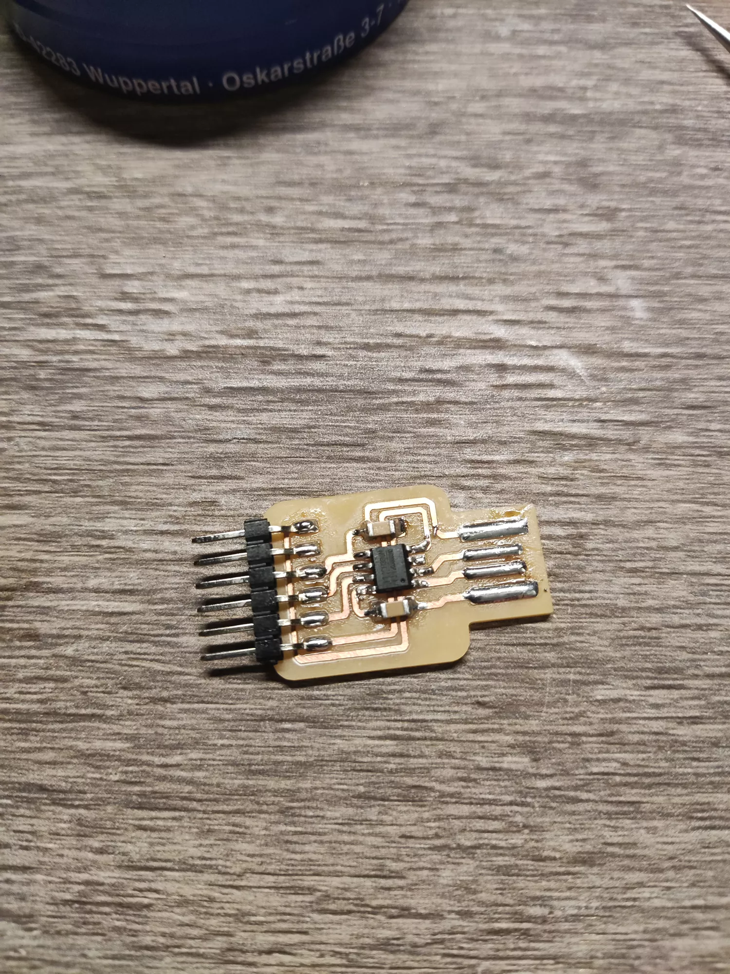
Soldered, Assembled FDTI Board
.
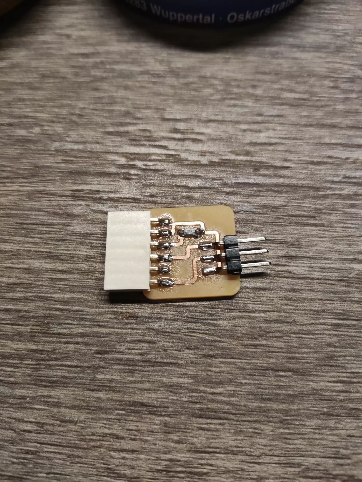
Soldered, Assembled UPDI Board
.
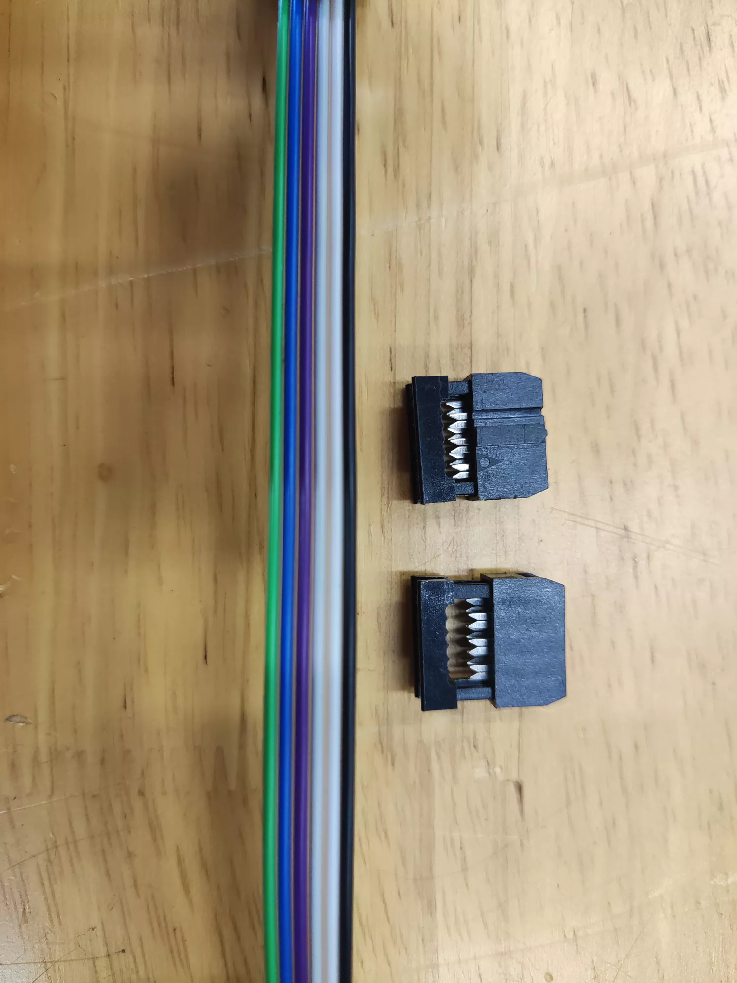
Programming Cable
A ribbon cable and two insulation displacing connectors
(IDC) connectors are needed.
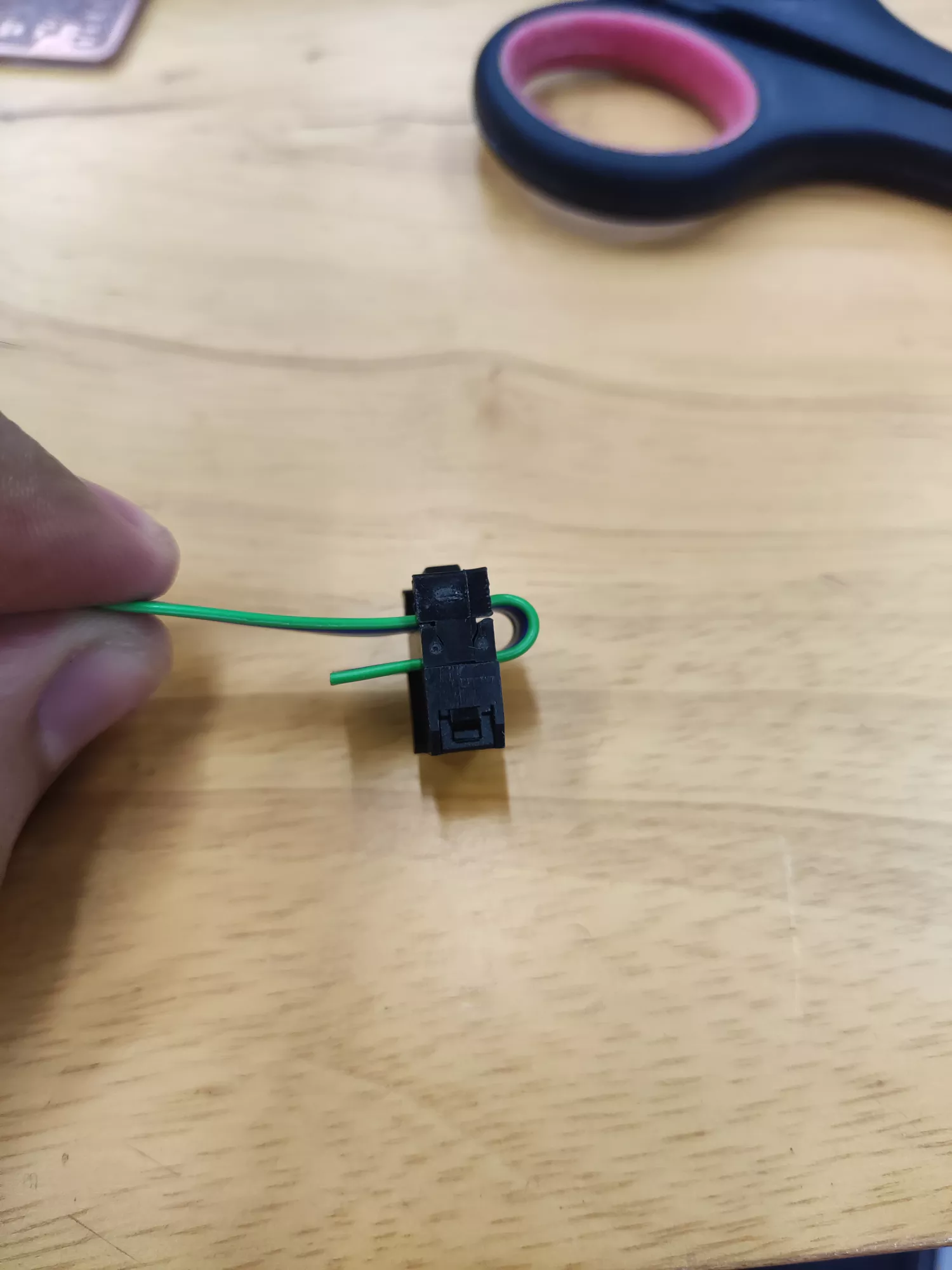
Crimping
The ribbon cable is inserted into the IDC connector.
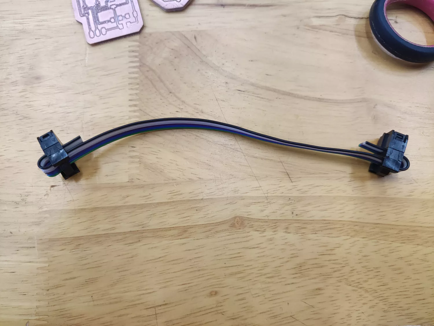
Completed Cable
The connectors are attached at both ends.